Ultrasonic Sensor
Aggregazione dei criteri
Ultrasonic Sensor
The HC-SR04 Ultrasonic Sensor enables non-contact measurement within 2cm and 400 cm range with an estimated precision of 3 mm.
Operating principle:
- It consists of two ultrasonic transducers.
- Transmitter: converts an electrical signal
into 40KHz ultrasonic sound pulses.
- Receiver: listens to the transmitted pulses. It responds with an output pulse whose amplitude allows the distance travelled by the pulse to be determined.
The sensor uses four connectors: power supply, trigger (activates the
ultrasonic sound pulses), echo (produces a pulse when the reflected signal is
received) and ground.
Mounting the LED and the ultrasonic sensor
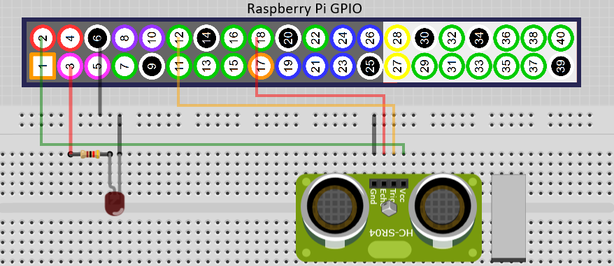
We started our project by connecting the 5mm red LED and the ultrasonic sensor on the Raspberry Pi:
- Connecting the LED to the Raspberry Pi
requires a resistor to limit the current amount; otherwise, it will burn
out. The most extended terminal of the LED is connected to pin 3 of the
GPIO (interposing the 1kΩ resistor), and the other terminal is connected
to pin 6 (GND).
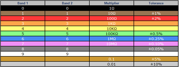
How to identify a 1kΩ resistor? Coloured bands applied to the body of the resistance represent the characteristics of the resistors (resistivity, multiplier, tolerance):

The
following table shows the meaning of each colour according to the position of
the band:
You can access a colour code calculator of the resistors by clicking here.
- The ultrasonic sensor has four connectors that connect to the GPIO pins of the Raspberry Pi according to the following scheme: